
Every year, our quality team rejects roughly 8% of incoming components before they ever reach our assembly line supplier certifications 1. Why? Because a single faulty capacitor or misaligned reflector can turn your branded device into a warranty nightmare. The pain is real—your customers complain, your reputation suffers, and margins evaporate.
You should inspect four critical production stages at a shockwave therapy machine factory: incoming component verification, in-production quality checkpoints, final functional testing, and pre-shipment packaging inspection. Each stage targets specific failure modes that directly impact device longevity, treatment consistency, and patient safety.
Let me walk you through each stage so you know exactly what to require from your supplier. These insights come from years of refining our own processes to meet the demands of brand owners in the US and Europe.
How can I audit the incoming component quality to ensure my shockwave machines last for years?
Our engineers learned this lesson the hard way years ago. A batch of substandard piezoelectric crystals 2 passed visual inspection but failed acoustic testing within three months of clinical use. The cost of recalls exceeded the savings from cheaper parts by a factor of ten.
To audit incoming component quality, verify supplier certifications, conduct material composition testing, measure critical dimensions against specifications, and perform sample electrical and acoustic tests. Focus on high-voltage cables, electrodes, reflectors, piezoelectric arrays, and membrane materials—these components determine device lifespan and treatment efficacy.
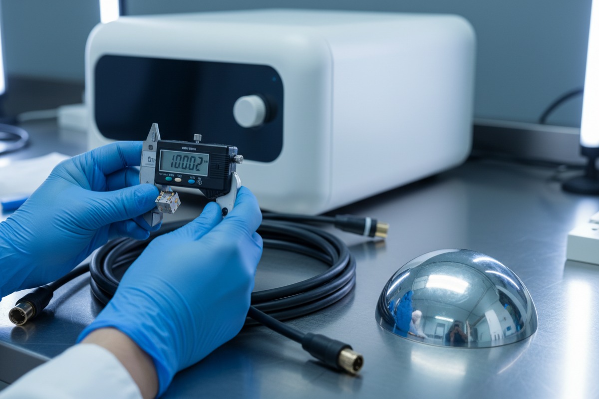
Why Component Quality Matters More Than Price
The shockwave generation mechanism relies on precise interactions between electrical and mechanical parts. A reflector with a 0.5mm deviation from spec can shift the focal point, reducing treatment effectiveness. A high-voltage cable with weak insulation can fail after 50,000 cycles instead of the expected 500,000.
When we source components, we require certificates of conformance from sub-suppliers. But certificates alone are not enough. We verify claims through our own testing protocols.
Critical Components Requiring Inspection
| Component | Key Inspection Parameters | Failure Risk if Skipped |
|---|---|---|
| High-voltage cables | Insulation resistance, conductor continuity, bend radius tolerance | Electrical failure, safety hazard |
| Piezoelectric crystals | Electrical impedance, frequency response, surface uniformity | Inconsistent energy output |
| Reflectors (elliptical/parabolic) | Surface geometry, coating adhesion, dimensional accuracy | Focal point deviation |
| Membranes | Thickness uniformity, elasticity, chemical compatibility | Fluid leaks, contamination |
| Electrodes | Material composition, surface finish, gap distance | Spark inconsistency, rapid wear |
Testing Methods We Recommend
For high-voltage components, insulation resistance testing at 1.5x operating voltage reveals weak spots. For piezoelectric arrays, impedance analyzers check each crystal element individually. Reflector geometry requires coordinate measuring machines (CMM) 3 with sub-millimeter accuracy.
We also test a random sample from each incoming batch under accelerated stress conditions. This means running components through thermal cycling and vibration tests that simulate years of clinical use in days.
Traceability Starts Here
Every component receives a unique lot number linked to supplier data, test results, and receiving date. If a problem surfaces later, we trace it back to the source within hours. Your supplier should provide this traceability documentation on request.
What in-production quality control checkpoints should I require to avoid performance issues later?
On our production floor, we stop assembly at seven defined checkpoints. Each stop represents a potential failure mode that becomes ten times harder to fix once the next stage begins. Skipping checkpoints to meet deadlines always costs more in the end.
Require in-production checkpoints at coil-magnet-electrode alignment, fluid system assembly, electrical safety verification, mechanical durability testing, handpiece integration, software calibration, and acoustic output validation. These checkpoints catch alignment errors, leaks, electrical faults, and output inconsistencies before final assembly locks them in.
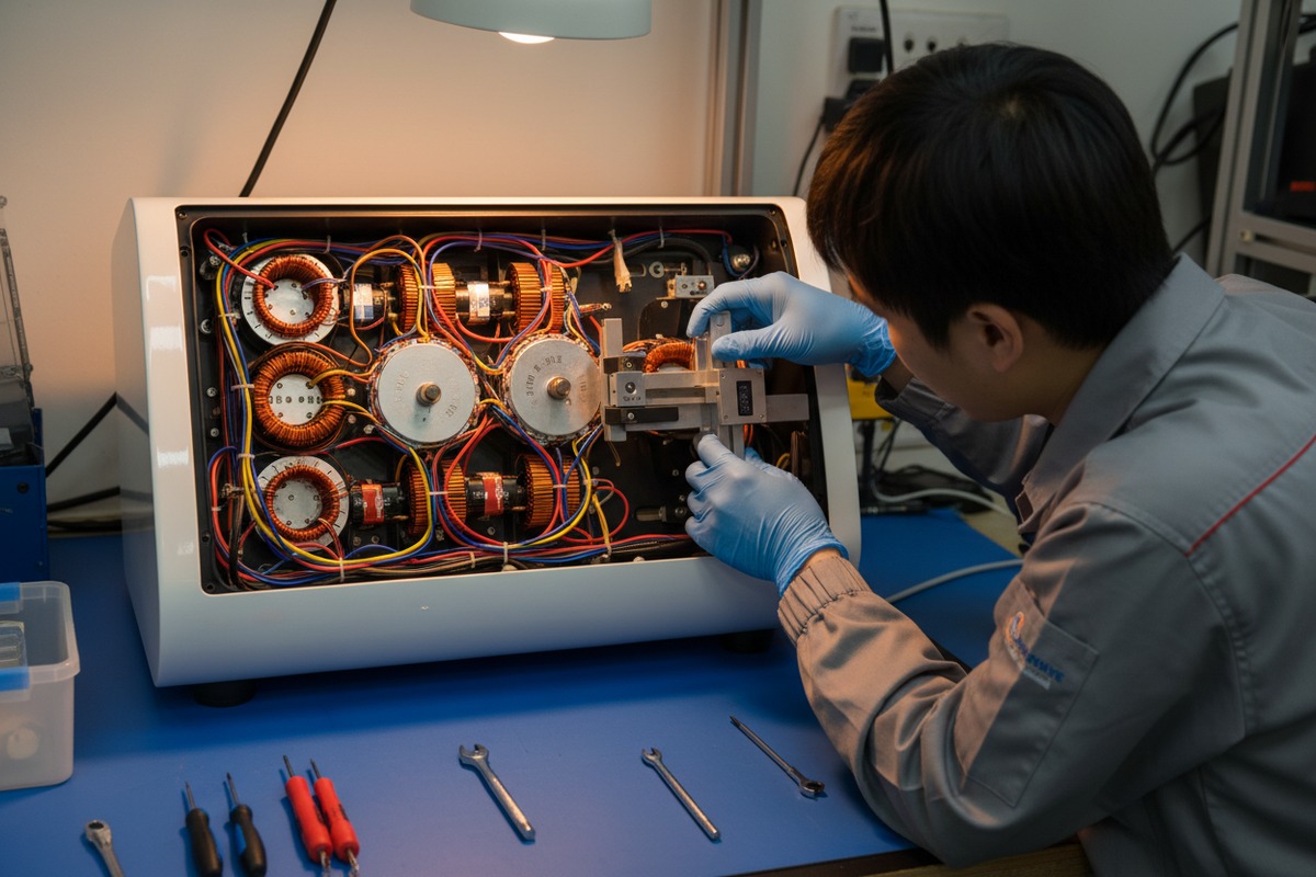
Checkpoint 1: Coil-Magnet-Electrode Alignment
Electromagnetic shockwave generation depends on precise concentricity between coils, magnets, and electrodes. Our technicians use dial indicators and precision jigs to verify alignment within 0.1mm tolerance. Misalignment causes uneven energy distribution and accelerated wear.
Checkpoint 2: Fluid System Assembly
Water or saline serves as the acoustic transmission medium. Any air bubble in the fluid cavity creates a dead zone in the shockwave field. We pressure-test every fluid chamber to 1.5 bar and inspect visually for bubbles under UV light. Membrane seals undergo pull tests to verify bond strength.
Checkpoint 3: Electrical Safety Verification
High-voltage systems demand rigorous safety checks. We measure insulation resistance, ground continuity, and leakage current at this stage. Emergency shutdown circuits receive functional tests under simulated fault conditions.
| Checkpoint | Test Method | Accept/Reject Criteria |
|---|---|---|
| Coil alignment | Dial indicator measurement | ≤0.1mm deviation |
| Fluid chamber | Pressure hold at 1.5 bar for 10 min | No pressure drop |
| Insulation resistance | Megohmmeter at 500V DC | ≥100 MΩ |
| Ground continuity | Low-resistance ohmmeter | ≤0.1 Ω |
| Leakage current | IEC 60601 test setup 4 | ≤100 µA |
Checkpoint 4: Mechanical Durability
The handpiece pivot mechanism sees thousands of adjustments over its service life. We cycle the pivot 5,000 times and verify that engagement force and angle accuracy remain within spec. Spline mechanisms undergo similar endurance testing.
Checkpoint 5: Handpiece Integration
When the handpiece connects to the main unit, we verify cable continuity, communication protocols, and mechanical locking. A loose connection here causes intermittent failures that frustrate clinicians and erode brand trust.
Checkpoint 6: Software Calibration
Each unit's control board receives firmware specific to its hardware characteristics. We calibrate energy output, frequency response, and display accuracy. Treatment presets are verified against expected parameters.
Checkpoint 7: Acoustic Output Validation
Before final assembly, we measure acoustic pressure at the focal point using calibrated hydrophones 5. This confirms that the assembled shockwave generator performs as designed. Any unit outside the ±10% energy tolerance returns to the line for adjustment.
Documentation at Every Stop
Technicians record pass/fail results, measurements, and timestamps at each checkpoint. This data feeds into our quality management system 6 and accompanies the device throughout its lifecycle.
Which final functional tests must my supplier perform to guarantee every unit meets my brand standards?
When a device leaves our facility bearing your brand, it carries your reputation. Our final testing protocol takes 45 minutes per unit because shortcuts here become customer complaints later. Every parameter that matters clinically gets verified.
Your supplier must perform final functional tests including full power-up sequences, energy output verification across all settings (5–200 mJ), frequency stability testing (1–16 Hz), acoustic field mapping, safety system validation, thermal stability under continuous operation, and user interface functionality checks. Each test must generate documented evidence traceable to the unit's serial number.

Energy Output Verification
Clinicians depend on consistent energy delivery. We test output at minimum (5 mJ), midpoint (100 mJ), and maximum (200 mJ) settings. Each measurement compares against calibrated reference standards. Deviation beyond ±5% triggers recalibration or rejection.
Frequency Stability Testing
Treatment protocols specify frequencies from 1 Hz to 16 Hz. We verify that the device maintains selected frequency within ±0.5 Hz across a 60-second test run. Frequency drift indicates control circuit problems that worsen over time.
Acoustic Field Mapping
Using a hydrophone array in a water tank, we map the pressure distribution around the focal point. The focal zone must align with the applicator tip within 2mm. Pressure intensity must match design specifications for effective tissue penetration.
| Test Category | Parameters Verified | Equipment Used |
|---|---|---|
| Energy output | 5, 100, 200 mJ accuracy | Calibrated energy meter |
| Frequency | 1, 8, 16 Hz stability | Digital oscilloscope |
| Focal accuracy | X, Y, Z position within 2mm | Hydrophone array |
| Pressure intensity | Peak positive/negative pressure | Calibrated hydrophone |
| Thermal stability | Surface temp after 30 min operation | IR thermometer |
Safety System Validation
We simulate fault conditions to verify that emergency stops, overcurrent protection, and thermal cutoffs activate correctly. A device that fails safety testing never ships—no exceptions.
Thermal Stability Under Continuous Operation
Clinical sessions may last 20–30 minutes. We run devices continuously for 30 minutes at maximum output and monitor internal and surface temperatures. Any unit exceeding thermal limits undergoes engineering review.
User Interface Functionality
Every menu path, button, and display element receives manual verification. The 8-inch LCD must show accurate parameters. The foot pedal switch must respond consistently. Treatment presets must apply correct settings.
Bullet and Applicator Head Durability
For pneumatic systems, we verify bullet condition and applicator head performance. Specifications indicate bullet lifetime of 3 million shocks. We verify that new bullets meet impact force consistency requirements.
Documentation Package
Each unit generates a test report including serial number, test date, technician ID, all measured values, and pass/fail status. This package accompanies the device and supports warranty claims.
How do I inspect the pre-shipment packaging to prevent any cosmetic or internal damage during transit?
We once shipped 50 units to a US distributor using standard foam packaging. Seven arrived with cracked display bezels. The shipping cost was a fraction of the loss—replacement parts, labor, customs delays, and damaged customer confidence. That experience reshaped our packaging protocols.
Inspect pre-shipment packaging by verifying cushioning adequacy for shock and vibration, moisture barriers for humidity protection, secure handpiece and accessory compartments, correct labeling and documentation, and drop-test certification. Packaging must protect the device through 20+ handling transfers and climate variations during international transit.
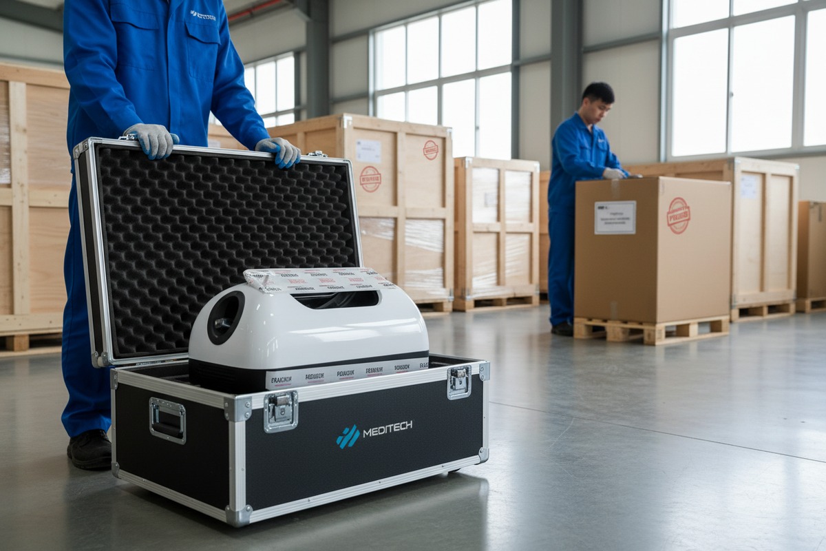
Packaging Design Requirements
Shockwave devices contain precision optics, sensitive electronics, and fluid-filled chambers. Packaging must absorb impacts from drops up to 76cm (standard shipping drop height) and vibrations across the 5–200 Hz spectrum typical of truck and air transport.
Cushioning and Shock Absorption
We use molded EPE foam inserts custom-fitted to each device profile. Critical components receive additional localized cushioning. The handpiece sits in a dedicated compartment to prevent contact with the main unit.
Moisture Protection
Ocean freight containers can reach 90% humidity. We seal devices in moisture-barrier bags 7 with desiccant packs. Humidity indicators inside the bag reveal if moisture exposure occurred during transit.
| Packaging Element | Specification | Verification Method |
|---|---|---|
| Outer carton | Double-wall corrugated, ECT 48 | Visual + caliper measurement |
| Foam cushioning | 45 kg/m³ density EPE, 50mm minimum | Density test + thickness check |
| Moisture barrier | 4-mil aluminum foil laminate | Visual inspection |
| Desiccant | 100g silica gel per cubic foot | Weight verification |
| Humidity indicator | 30/40/50% color-change cards | Placement confirmation |
Accessory Security
The packing list typically includes the host unit, handpiece, working heads, bullets, pedal switch, power cord, and manual. Each item occupies a designated position. Loose accessories become projectiles during handling and cause internal damage.
Labeling and Documentation
Shipping labels must include correct weight, dimensions, and handling symbols (fragile, this side up, keep dry). Commercial invoices, packing lists, and regulatory documents travel with the shipment in waterproof pouches.
Drop and Vibration Testing Certification
We perform ISTA 2A testing 8 on packaging designs. This protocol simulates distribution hazards through controlled drops, vibrations, and compression. Packaging that fails testing gets redesigned before production use.
Pre-Shipment Inspection Checklist
Before sealing each carton, inspectors verify:
- Device serial number matches documentation
- All accessories present per packing list
- No visible cosmetic defects
- Moisture barrier sealed correctly
- Humidity indicator showing acceptable level
- Foam inserts properly positioned
- Outer carton intact and labeled
Photographic Documentation
We photograph each unit before packaging and each sealed carton. These images provide evidence of condition at shipment and support damage claims if problems arise.
Conclusion
Inspecting shockwave therapy machines at incoming, in-production, final testing, and packaging stages catches defects before they become your problem. Require documented evidence at each checkpoint. Your brand depends on it.
Footnotes
1. Provides information on the importance and types of supplier certifications in quality management. ↩︎
2. Explains the science, discovery, and applications of piezoelectric materials. ↩︎
3. Describes the function, components, and application of CMM in precision measurement. ↩︎
4. Details the international standard for medical electrical equipment safety. ↩︎
5. Provides information on hydrophones and their use in acoustic measurements and calibration. ↩︎
6. Replaced with the official ISO page for ISO 9001, which defines quality management systems. ↩︎
7. Describes the purpose and types of moisture barrier packaging for sensitive goods. ↩︎
8. Explains the ISTA 2A standard for packaged products weighing 150 lb (68 kg) or less. ↩︎

 English
  Español de México
  Deutsch
  Français
  العربية
  Русский