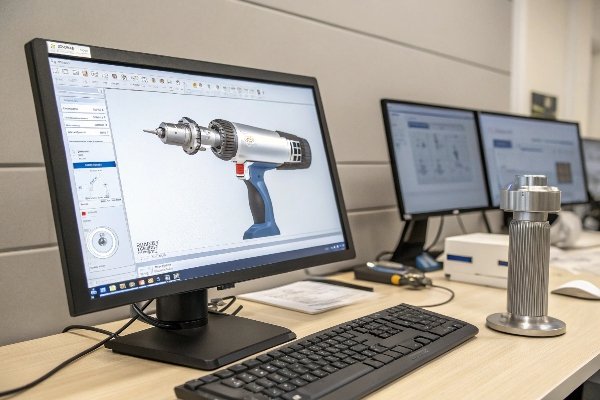
I often get this request at the very start of a project: “Can you share drawings or 3D models so our team can review fit and branding?” Yes—when the scope and protections are clear. Using a standard mutual NDA template and guidance from WIPO 1 keeps both sides protected from day one.
Most reputable suppliers do provide technical drawings and 3D models for custom shockwave machines under NDA. The level of detail depends on scope, IP risk, and order commitment. Early stages use simplified models; later stages include full interfaces and mounting data.
A clean process keeps IP safe, timelines short, and engineering decisions visible. The following sections explain typical file types, what detail to expect, when files are shared, how much freedom customers have to edit, and when fees apply.
How detailed are supplier design files?
I like to start with the end in mind. I ask engineering teams exactly which decisions they need the files to support, so I can send the minimum that lets them move forward fast. For dimensioning and tolerances, most customers reference GD&T per ASME Y14.5 2 to avoid ambiguity between shops.
Supplier files range from simple “envelope” models to fully dimensioned manufacturing drawings. For most OEM/ODM projects, suppliers share interface-complete CAD (for fit, mounting, cable paths) while keeping proprietary internals abstracted or “black-boxed.”
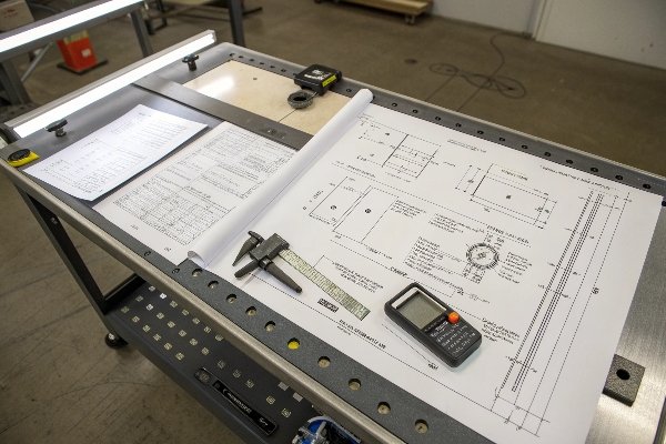
Design data usually follows a staged release, aligned to risks and decisions.
Typical levels of detail (LOD)
- LOD-E (Envelope): External size, keep-out zones, connector locations, mounting hole patterns. No internals. Good for cart design, clinic layout, or packaging.
- LOD-I (Interface-complete): Adds mechanical interfaces, thread types, datum references, cable bend radii, and heat-vent keep-outs. Good for integration and DFMA review.
- LOD-F (Fabrication subset): Includes 2D fabrication drawings for non-proprietary brackets, panels, and carts with tolerances and finishes.
- LOD-P (Proprietary internals): Full assemblies of handpieces, energy modules, PCB stacks, or transducers. Often withheld or provided as simplified “blobs” with accurate mass/COG.
- LOD-S (Service views): Exploded diagrams, torque specs, wear-part callouts, and maintenance sequences for training.
File types seen in shockwave projects
- CAD: STEP (.stp) per ISO 10303 “STEP” 3, IGES (.igs) with history dating to the NIST IGES resources 4, and Parasolid (.x_t/.x_b) from Siemens Parasolid 5.
- Drawings: PDF for read-only, DWG/DXF for 2D, and sometimes native CAD for jointly engineered parts.
- Meta: BOM extracts, surface finish tables, paint codes (RAL/Pantone), thread tables, and torque charts.
- UX collateral: Screen layout wireframes (PNG, Figma exports), label artwork (AI/PDF), and laser-etch files (DXF).
Table 1 — Detail level vs. decision it unlocks
| Detail Level (LOD) | What’s included | What decisions it supports | IP sensitivity |
|---|---|---|---|
| LOD-E (Envelope) | Overall size, keep-outs, mounting | Furniture, packaging, space planning | Low |
| LOD-I (Interface) | Holes, threads, datum, cable path | Cart/mech integration, DFMA checks | Medium |
| LOD-F (Fabrication) | 2D drawings w/ tolerances & finishes | Outsourced sheet metal, panels | Medium–High |
| LOD-P (Proprietary) | Internals of handpiece/power module | Deep co-development, validation | High |
| LOD-S (Service) | Exploded views, torque, wear parts | Service manuals, training | Medium |
Suppliers release higher LOD data as trust grows, scope stabilizes, and orders move from concept to build.
Can 3D models be modified by customers?
I hear strong R&D teams say, “We will adjust your STEP to speed enclosure or cart design.” That is fine when guardrails are clear. Many teams also keep a PLM single source of truth—see Product Lifecycle Management overview 6—to track revisions and approvals.
Customers may modify shared 3D models for integration and packaging, provided contract terms restrict redistribution and prohibit changes that affect performance or safety. Suppliers usually require change proposals for any interface that touches function or compliance.

Here is how editing works in practice.
What customers can usually change
- Non-functional geometry around the unit: Cutouts in a cart, docking brackets, cable channels, and label panels.
- Brand and UI elements: Front panel bezels, handle shapes, color trims, and badge bosses, as long as clearances remain.
- Packaging and casework: Foam inserts, flight cases, clinic furniture adaptations.
What requires supplier approval
- Mounting interfaces: Hole patterns, threads, and datum features that ensure alignment and vibration control.
- Thermal and airflow paths: Vent size, mesh density, or fan duct shapes that influence cooling and acoustic comfort.
- EMC and shielding: Conductive gaskets, grounding tabs, or shield cans that protect compliance margins.
- Handpiece and transducer geometry: Anything that might change energy delivery, ergonomics, or biocompatibility.
Safe workflow for edits
- Work on derivative copies, not the master model.
- Keep a revision log with date, change, and rationale.
- Send redlines or overlay screenshots for fast supplier review.
- Request a DDID (design deviation ID) when a quick trial is needed.
- Fold accepted edits back into the supplier’s PLM to stay traceable.
Table 2 — Common file formats and recommended use
| Format | Best use | Pros | Caveats |
|---|---|---|---|
| STEP (.stp) | Neutral exchange for solid models | Stable, widely supported | Loses feature history |
| IGES (.igs) | Curves/surfaces for styling | Good for freeform | Can import messy |
| Parasolid (.x_t) | High-fidelity exchange | Precise, robust booleans | Not all CAD imports |
| Native SW/Inventor | Deep co-dev with same CAD | Feature tree preserved | Version lock, IP risk |
| PDF drawings | Procurement & QA | Uneditable, clear | Not parametric |
If stakeholders don’t have CAD tools, viewer formats like eDrawings 7 or 3D PDF (see Adobe’s 3D PDF guide) support page 8 let teams measure and annotate without exposing native files.
I get asked for CAD “early” because teams want to freeze carts and packaging while branding evolves. The timing depends on risk. Automotive-style release packages sometimes align with PPAP gates; see the AIAG PPAP reference 9. Aerospace-style first builds may use FAI (AS9102) documentation from SAE International 10.
Yes. CAD is typically shared in phases before production: concept envelope at RFQ, interface-complete during DFM, and fabrication drawings at design freeze. Final as-built files are released at PPAP/FAI or after the pilot run, depending on contract.

A phased handoff keeps teams aligned and avoids rework.
Typical timeline for sharing
- RFQ / Concept (Week 0–2): LOD-E envelope and key keep-outs. Enough for space planning and early cart sizing.
- DFM / EVT (Week 2–6): LOD-I interface models and preliminary drawings for panels and brackets. Supplier and customer run tolerance stacks.
- DVT / Design Freeze (Week 6–10): LOD-F fabrication drawings for outsourced parts and labeled “Release Candidate.”
- PVT / Pilot (Week 10–14): Service views (LOD-S) and updated CAD reflecting pilot corrections.
- Mass Production: As-built pack with revision tags, QC fixtures, torque charts, and label artwork.
What if the clinic needs files even earlier?
Suppliers may share read-only or watermarked models. Some will provide viewer files (e.g., eDrawings, 3D PDFs) so stakeholders can measure without extracting sensitive geometry.
Contract items that keep schedules tight
- A definition of done for each CAD batch.
- A change window with cut-off dates before tooling or PCB fab.
- A review SLA (e.g., 48–72 hours) for redlines.
- A single source of truth (PLM link or vault) to avoid version drift.
Do suppliers charge for design models?
I get this question from purchasing leads who must protect budgets: “Are CAD files free?” The honest answer is, it depends on depth and rights.
Many suppliers include envelope and interface CAD at no extra charge once an order is in place. Detailed fabrication drawings, native CAD, and proprietary assemblies often require either a minimum order quantity (MOQ), an NRE fee, or a licensed access model.
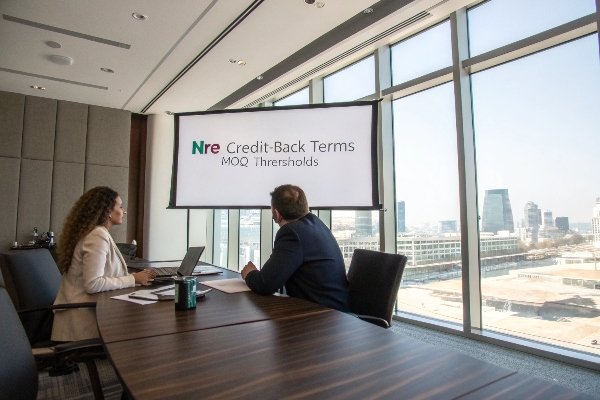
Charging policies reflect the real cost of engineering time, quality documentation, and IP protection.
Common charging models
- Included with order: LOD-E/LOD-I, drawings for customer-owned parts, label artwork, and packaging die-lines.
- NRE (Non-Recurring Engineering): One-time fee covering co-development, DFM iterations, and validation. Often credited back after a volume threshold.
- Licensed access: Annual fee for native CAD, parametric libraries, or API docs; tied to user count and scope.
- Escrow or “black-box” compromise: Supplier keeps internals private but shares accurate mass/COG and interfaces at no fee.
What influences cost
- Depth of disclosure: Internals vs. interfaces only.
- Revision count: How many design loops are included.
- Ownership terms: Whether the customer gains derivative rights.
- Support scope: CAD helpdesk, conversion, and re-exports.
Table 3 — Typical fee patterns by deliverable
| Deliverable | Often included | Sometimes charged | Notes |
|---|---|---|---|
| Envelope STEP + keep-outs | ✅ | — | Standard after NDA/PO |
| Interface-complete CAD | ✅ | — | Needed for DFM/integration |
| Fabrication drawings (2D) | — | ✅ | For customer-owned parts |
| Native CAD with features | — | ✅ | License or NRE likely |
| Proprietary internals | — | ✅ | Usually black-boxed |
| Service manuals (exploded) | ✅ | — | After pilot build |
| Viewer files (3D PDF) | ✅ | — | Helpful for non-CAD teams |
Clear commercial terms remove friction and protect both sides.
Conclusion
Most suppliers share drawings and 3D models in phases under NDA. Early files cover envelopes and interfaces; later files add fabrication detail. Customers can modify models for integration, but functional interfaces need approval. CAD access is often included with orders; deeper or native packages may require NRE or licensing.
Footnotes
1. WIPO explains NDAs and IP basics for cross-border projects. ↩︎
2. ASME Y14.5 defines GD&T to communicate precise requirements. ↩︎
3. ISO 10303 (STEP) is the neutral CAD data exchange standard. ↩︎
4. NIST hosts IGES resources and historical specifications. ↩︎
5. Siemens Parasolid describes the geometric kernel behind many CAD tools. ↩︎
6. PLM overview shows how teams govern revisions and releases. ↩︎
7. eDrawings Viewer lets non-CAD users open and measure models. ↩︎
8. Adobe’s guide shows how to view 3D models in PDFs. ↩︎
9. AIAG PPAP explains production part approval deliverables. ↩︎
10. SAE AS9102 defines First Article Inspection documentation. ↩︎

 English
  Español de México
  Deutsch
  Français
  العربية
  Русский