
When our engineering team receives customization requests, one question comes up repeatedly. Buyers want to know what technical files they will receive. They worry about verifying designs before production starts. Without proper documentation, quality control becomes guesswork.
Yes, reputable suppliers typically provide technical drawings and 3D CAD models during shockwave therapy machine customization. The extent of documentation depends on the project scope, intellectual property agreements, and customization level. Most manufacturers share design renderings, dimensional drawings, and component specifications to ensure client approval before mass production begins.
This article answers the most common questions about design documentation. We cover CAD models, technical drawings 1, branding verification, and engineering files for quality control. Let us walk through each concern step by step.
Can I get the 3D CAD models to verify the design before I start my custom production?
Our clients often ask about CAD files early in discussions. They want visual confirmation before committing to production. This makes perfect sense. A 3D model reveals problems that flat images cannot show.
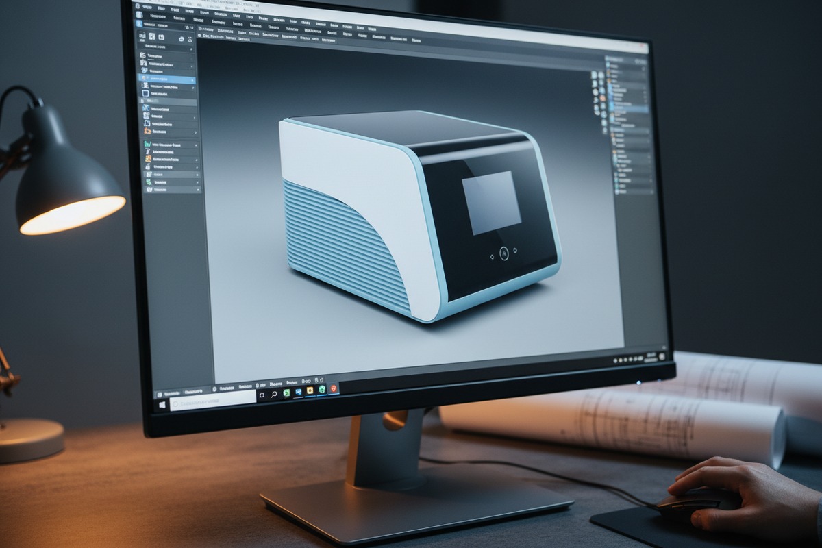
Most professional shockwave therapy machine manufacturers provide 3D CAD models during the design approval phase. These models allow you to rotate, zoom, and inspect every angle of your customized device. You can verify dimensions, check component placement, and confirm aesthetic details before tooling begins.
Why CAD Models Matter for Custom Projects
When our design team creates a customized shockwave therapy machine 2, we build everything in 3D software first. This digital prototype serves multiple purposes. It shows you exactly what the finished product will look like. It also helps our engineers test fit and function virtually.
The CAD model is not just a pretty picture. It contains precise measurements. Every curve, every button position, every ventilation slot has exact coordinates. This precision matters when you need the device to fit specific clinic spaces or match existing equipment.
What Information CAD Models Include
| CAD Model Component | What You Can Verify | Why It Matters |
|---|---|---|
| External Shell Design | Overall shape, panel layout, screen position | Ensures aesthetic approval |
| Internal Component Layout | Circuit board placement, cable routing | Confirms serviceability |
| Dimensional Data | Height, width, depth, weight distribution | Validates shipping and storage needs |
| Material Specifications | Plastic type, metal components, surface finish | Confirms durability expectations |
| Assembly Structure | How parts connect, screw positions | Supports future maintenance planning |
Limitations on CAD File Sharing
Here is something important to understand. Suppliers will show you CAD models, but they may not hand over the actual files. There is a good reason for this. The CAD files contain proprietary design information. Our reflector geometry, for example, took years to develop. Sharing editable files risks intellectual property theft 3.
Most manufacturers offer viewing access through secure portals. You can inspect the model thoroughly. You can request changes. But the source files typically stay with the supplier. This protects both parties.
Some clients negotiate full file transfer for co-development projects. This requires separate intellectual property agreements. The scope of customization matters here. Simple branding changes rarely justify full file access. Complete ground-up development often does.
Will your engineers provide technical drawings so I can ensure the internal components meet my standards?
During our factory tours, purchasing managers always want to see inside the machines. They ask about component quality. They want documentation they can review with their own engineers. Technical drawings answer these questions.
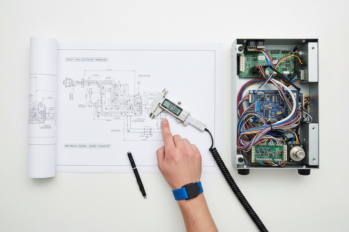
Yes, our engineers provide detailed technical drawings covering internal components, circuit layouts, and mechanical assemblies. These 2D drawings include dimensions, tolerances, material callouts, and component specifications. They enable your technical team to verify that all internal parts meet your quality standards before production approval.
Types of Technical Drawings Available
Different drawings serve different purposes. Understanding what to request saves time and prevents misunderstandings.
Assembly Drawings show how components fit together. They identify each part with reference numbers. They indicate screw torque values and assembly sequences. Your quality control team uses these during inspections.
Detail Drawings focus on individual components. They show exact dimensions with tolerances. They specify surface finishes and material grades. These drawings matter when you need to verify that suppliers use the correct parts.
Schematic Drawings map electrical connections. They show circuit pathways, component values, and safety features. These help your engineers understand the device logic and troubleshoot potential issues.
Component Verification Process
| Drawing Type | Information Provided | Verification Purpose |
|---|---|---|
| Mechanical Assembly | Part positions, fastener specs, clearances | Check physical build quality |
| Electrical Schematic | Circuit paths, component ratings, grounding | Verify safety compliance |
| PCB Layout | Board dimensions, trace routing, component placement | Confirm electronic design standards |
| Hydraulic/Pneumatic | Pressure ratings, flow paths, seal specifications | Validate performance capabilities |
| Exploded View | All components separated with labels | Support maintenance documentation |
How to Use Drawings for Quality Assurance
We recommend a structured review process. First, have your engineering team study the drawings thoroughly. Mark any areas of concern. Then schedule a technical call with our engineers to discuss questions.
Pay special attention to safety-critical components. The shockwave generator, power supply, and grounding systems deserve extra scrutiny. Ask for material certifications for these parts. Request test data where available.
One common mistake is reviewing drawings too quickly. Some clients glance at documents and approve immediately. Weeks later, during production, they discover issues. Taking time upfront prevents costly changes later.
Regulatory Documentation Connection
Technical drawings also support regulatory submissions. If you sell in markets requiring FDA clearance or CE marking, you need detailed design documentation. Our drawings follow ISO 13485 documentation standards 4. This makes your regulatory filings smoother.
We maintain full design history files for every customized project. These files include all drawings, change records, and approval signatures. You can request copies for your own regulatory archives.
How do I review the design renderings to confirm my branding is applied correctly to the machine?
Branding mistakes are expensive. We have seen clients approve designs only to reject finished products because logos looked wrong. The color was slightly off. The placement seemed different on the actual device. Proper rendering review prevents these problems.
Suppliers provide photorealistic design renderings showing your branding exactly as it will appear on the finished machine. These renderings display logo placement, color matching, typography, and overall brand presentation. You should review renderings under multiple lighting conditions and request physical color samples for final approval.

The Rendering Review Process
When our design team applies your branding, we create multiple renderings. These show the device from different angles. Front view, side view, detail shots of the logo area. We also create renderings with different background lighting to simulate various clinic environments.
The rendering process follows specific steps. First, you provide brand assets. These include vector logo files, Pantone color codes 5, and brand guidelines. Our designers apply these to the 3D model. Then we generate high-resolution images for your review.
What to Check in Brand Renderings
| Branding Element | What to Verify | Common Issues |
|---|---|---|
| Logo Placement | Position, size, orientation | Logo appears smaller than expected on curved surfaces |
| Color Accuracy | Pantone match, consistency across panels | Screen colors differ from printed/physical colors |
| Typography | Font rendering, spacing, readability | Small text becomes illegible at actual size |
| Surface Integration | How branding sits on textured vs smooth areas | Logos distort on ribbed or curved panels |
| Secondary Branding | UI screens, packaging, accessories | Inconsistent brand application across touchpoints |
Physical Samples and Prototypes
Renderings have limitations. Computer screens display colors differently than physical materials. This is why we recommend physical samples for critical branding decisions.
For logo printing, we can provide sample panels with your branding applied. You see exactly how the ink sits on the plastic. You check color accuracy under real lighting. This extra step costs time but prevents expensive rework.
Some clients request full appearance prototypes. These are non-functional units built solely for visual approval. They show the complete external design with all branding applied. This investment makes sense for flagship products or high-volume orders.
Digital Proofing Tools
We use several digital tools to improve rendering accuracy. Calibrated monitors ensure our designers see colors correctly. We can share files in formats that preserve color profiles. Video calls allow real-time design discussions where you can request changes immediately.
For touchscreen interfaces, we provide UI mockups separately. These show how your brand appears on the device software. Screen colors can also be customized. We match button colors, background themes, and startup screens to your brand identity.
Can I access the engineering files to help my team manage quality control and pre-shipment inspections?
Quality control is where documentation proves its value. Our clients often send inspection teams or hire third-party inspectors. They need reference documents to check against. Without proper files, inspectors cannot verify that products meet specifications.
Qualified suppliers provide engineering documentation packages specifically formatted for quality control and inspection purposes. These packages include inspection checklists, acceptance criteria, test procedures, and reference specifications. Your team or third-party inspectors can use these documents to verify every unit before shipment.

Quality Control Documentation Package
When we prepare a customized order for production, we create a comprehensive documentation package. This package travels with the order through every production stage. It also goes to you for inspection reference.
The package includes several document types. Each serves a specific quality control function.
Document Types and Their Uses
| Document Type | Contents | QC Application |
|---|---|---|
| Inspection Checklist | Point-by-point verification items | Guides inspector through systematic review |
| Acceptance Criteria | Pass/fail specifications for each checkpoint | Defines clear quality boundaries |
| Test Procedures | Step-by-step functional testing instructions | Ensures consistent test methodology |
| Reference Photos | Images showing acceptable quality standards | Visual comparison for cosmetic inspection |
| Measurement Specs | Critical dimensions with tolerances | Enables dimensional verification |
Supporting Pre-Shipment Inspections
Pre-shipment inspection 6 is critical. This is your last chance to catch problems before products leave our facility. We support this process in several ways.
First, we schedule inspections at convenient times. Inspectors need adequate time to check units properly. Rushing leads to missed defects. We coordinate schedules to ensure thorough reviews.
Second, we provide workspace and equipment. Inspectors need tables, lighting, and measuring tools. We set up dedicated inspection areas when requested. This professional environment supports accurate assessments.
Third, our quality team remains available for questions. Inspectors sometimes encounter unfamiliar features. Our engineers can explain design intent and acceptable variations. This collaboration prevents unnecessary rejections.
Creating Your Own Inspection Protocols
We encourage clients to develop their own inspection procedures. Use our documentation as a starting point. Add checks specific to your market requirements. Customize the checklist to match your quality standards.
Some clients focus heavily on cosmetic quality. They add detailed visual inspection points. Others prioritize functional testing. They expand the electrical safety checks. Your inspection protocol should reflect what matters most to your customers.
Remote Inspection Options
Travel is not always practical. We offer video inspection services for clients who cannot visit our facility. Our quality team conducts inspections on camera. You watch in real-time and direct the process. This approach combines convenience with verification confidence.
We can also generate detailed inspection reports with photos. These reports document every checkpoint result. They provide evidence of quality verification for your records. Many clients use these reports for their own customer documentation.
Documentation Retention and Access
All engineering files are stored in our document management system 7. You can request copies at any time. We maintain records for a minimum of ten years. This supports warranty claims, regulatory inquiries, and future reorders.
For repeat orders, we retrieve the original documentation. This ensures consistency across production runs. Any updates or improvements are documented with revision histories. You always know exactly what specifications apply to your products.
Conclusion
Technical documentation is fundamental to successful shockwave therapy machine customization. From 3D CAD models 8 to inspection checklists, proper documents protect your investment. Work with suppliers who provide comprehensive files. Ask questions early. Review thoroughly before approving production.
Footnotes
1. Offers a comprehensive definition and explanation of technical drawings and their importance in engineering. ↩︎
2. Provides a general overview and medical uses of extracorporeal shockwave therapy. ↩︎
3. Defines intellectual property theft, its forms, and the damage it can cause to businesses. ↩︎
4. Details the ISO 13485 standard for quality management systems in the medical device industry. ↩︎
5. Explains the Pantone Matching System, its purpose, and use in standardizing colors. ↩︎
6. Describes pre-shipment inspection as a quality control process to verify product quality before shipment. ↩︎
7. Defines document management systems (DMS) and their role in storing, managing, and tracking electronic documents. ↩︎
8. Explains what 3D CAD software is, how it works, and its applications in design and engineering. ↩︎

 English
  Español de México
  Deutsch
  Français
  العربية
  Русский