When our production team first developed shockwave therapy equipment 1, we heard this concern constantly: “How do I know your painless claims are real?” Many distributors had been burned before. They bought machines with bold marketing promises, only to face client complaints and returns.
To verify painless technology claims, request engineering documentation including energy flux density specifications (0.08–0.6 mJ/mm²), ISO 14971 risk management reports, independent lab test results from ISO/IEC 17025 accredited facilities, and peer-reviewed clinical studies tied to the exact device model you plan to purchase.
This guide walks you through every step of the verification process ISO 14971 risk management reports 2. We will cover technical specs, quality control procedures, and collaboration opportunities. Let us dive into the details that protect your brand reputation.
How do I technically verify that your shockwave therapy machine delivers a truly painless experience for my clients?
Our engineers get asked this question weekly from US and European distributors ISO/IEC 17025 accredited facilities 3. The word "painless" appears everywhere in marketing. But without hard numbers, it means nothing. You need concrete specifications to make an informed decision.
Technically verify painless claims by examining energy flux density (EFD) ranges, pressure settings in bar units, pulse frequency options, and applicator design. Request calibration certificates showing output consistency within ±5% tolerance, and compare specifications against published clinical comfort thresholds.

Understanding Energy Flux Density
Energy flux density 4 determines how much energy hits the tissue per square millimeter. Lower EFD generally means less discomfort. Our machines operate in the 0.08–0.28 mJ/mm² range for comfort-focused treatments. Higher settings exist for stubborn conditions but require patient consent.
The table below shows typical EFD ranges and their applications:
| EFD Range (mJ/mm²) | Application Type | Comfort Level |
|---|---|---|
| 0.08–0.15 | Superficial soft tissue | High comfort |
| 0.15–0.28 | Moderate depth therapy | Moderate comfort |
| 0.28–0.60 | Deep tissue treatment | Lower comfort |
Pressure and Pulse Parameters
Radial shockwave machines 5 use air pressure measured in bar. Our devices offer 1.0–5.0 bar adjustable settings. Starting at lower pressures allows practitioners to gauge patient tolerance. The pulse frequency also matters. Faster pulses (15–20 Hz) feel different than slower ones (5–10 Hz).
When reviewing specifications, look for these elements:
- Adjustable pressure range with fine increments
- Multiple frequency settings for customization
- Real-time display showing actual output values
- Safety cutoffs preventing accidental over-delivery
Focused vs. Radial Technology
Focused shockwave 6 penetrates deeper but concentrates energy in small areas. Radial technology spreads energy across larger surfaces. For "painless" marketing, radial devices dominate because they distribute sensation more evenly.
Our production line includes both types. We clearly label which technology each model uses. Avoid suppliers who blur this distinction. Ask directly: "Is this focused or radial?" The answer affects everything from treatment protocols to client comfort expectations.
Calibration and Consistency
A machine might have perfect specifications on paper. But does it deliver consistent output unit after unit? We perform calibration checks using certified hydrophones and pressure sensors. Each device receives a unique calibration certificate before shipping.
Request calibration data showing:
- Output measurements at multiple settings
- Deviation percentages from target values
- Test equipment model and calibration dates
- Technician signatures and quality stamps
What engineering documentation can I review to confirm the stability and comfort of your painless technology?
In our experience exporting to North American clients, documentation requests have increased significantly. Sophisticated buyers now demand complete engineering files. They understand that marketing claims require technical backing.
Review ISO 14971 risk management files, design verification and validation reports, component traceability documents, electromagnetic compatibility test results, and Declaration of Conformity certificates. Cross-reference model numbers across all documents to ensure consistency.

Essential Documentation Checklist
When evaluating any shockwave therapy supplier, request these specific documents:
| Document Type | Purpose | What to Check |
|---|---|---|
| ISO 14971 Risk Report | Safety verification | Identified risks and mitigation measures |
| IEC 60601-1 Test Report | Electrical safety | Compliance with medical device standards |
| Design History File | Development traceability | Design inputs matching outputs |
| Calibration Certificates | Output accuracy | Deviation within acceptable limits |
| Declaration of Conformity | Regulatory compliance | Valid signatures and dates |
Understanding ISO 14971 Risk Management
This international standard requires manufacturers to identify potential hazards and implement controls. For shockwave devices, risks include tissue damage from excessive energy, electrical shock, and mechanical failure. Our risk management files detail every identified hazard.
Look for these elements in risk documentation:
- Hazard identification specific to shockwave therapy
- Severity and probability assessments
- Risk control measures implemented
- Residual risk evaluation after controls
A supplier who cannot produce ISO 14971 documentation likely lacks robust design processes. This standard is fundamental to medical device development worldwide.
Regulatory Pathway Evidence
For US markets, FDA 510(k) clearance 7 demonstrates substantial equivalence to predicate devices. We help clients understand which models have clearance and for which indications. The FDA database allows public verification of 510(k) summaries.
CE marking for European markets 8 requires assessment by Notified Bodies. The NANDO database lists authorized bodies. Verify that your supplier's certificates come from legitimate organizations.
Key regulatory checkpoints include:
- 510(k) summary matching exact model name
- CE certificate listing specific device type
- Notified Body number verifiable in NANDO
- Certificate expiration dates still valid
Component and Material Traceability
Stable performance requires quality components from reliable sources. Our engineering files trace every critical part to its supplier. This includes handpiece transducers, control board processors, and power supply units.
Ask suppliers about their component sourcing strategy. Do they use automotive-grade electronics? Medical-grade plastics? Traceability documents reveal these details. Cheaper components may function initially but fail faster under clinical use.
How does your quality control team test each unit to ensure the painless performance meets my brand's high standards?
When we calibrate our production equipment each morning, consistency is the goal. Your brand reputation depends on every unit performing identically. One faulty machine reaching your customer damages trust that took years to build.
Quality control testing includes incoming material inspection, in-process assembly checks, final output verification using calibrated instruments, 48-hour burn-in testing, cosmetic inspection, and packaging integrity verification. Each unit receives a unique test report documenting all results.
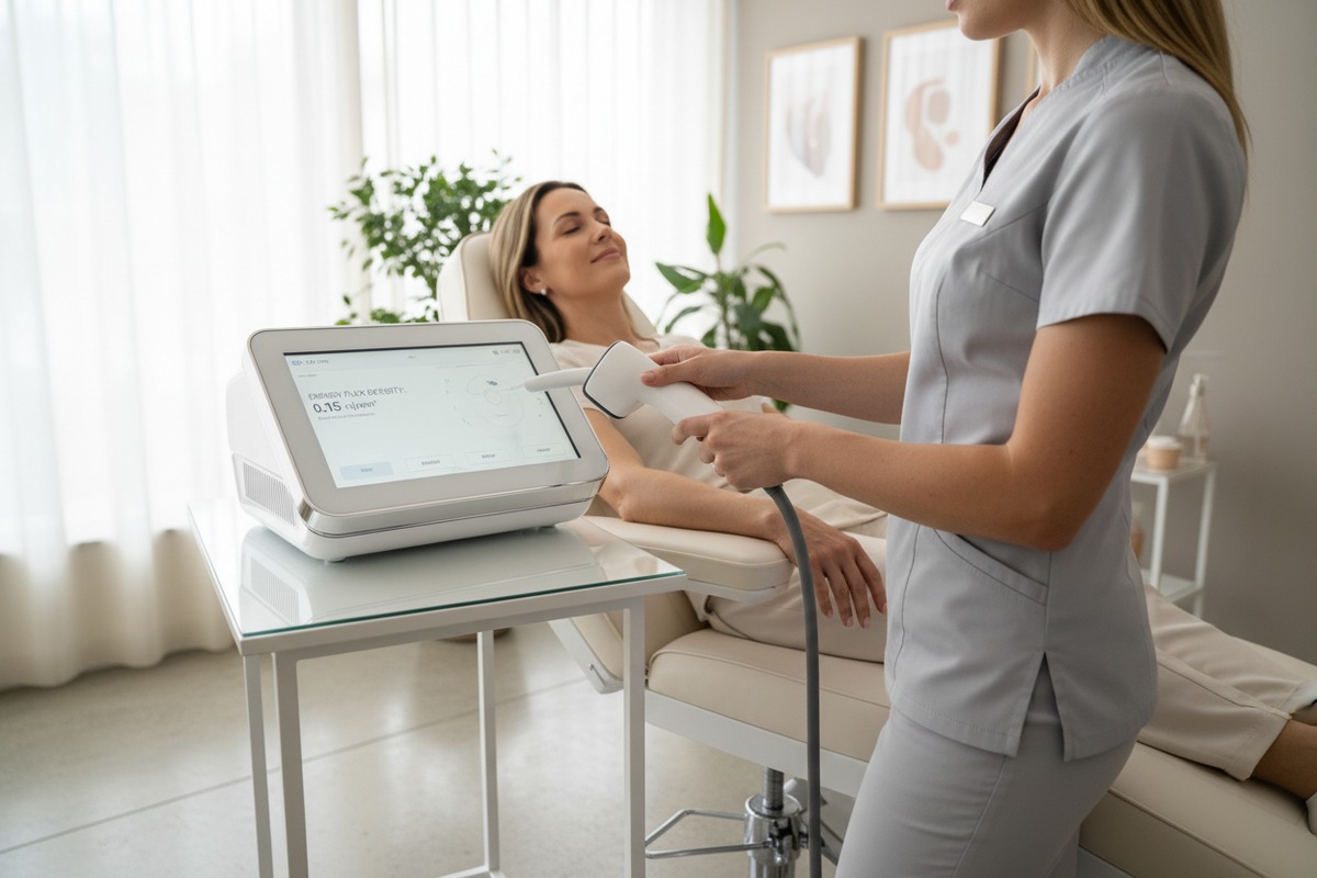
Incoming Quality Control
Quality begins before assembly starts. Our QC team inspects incoming components against specifications. Critical items like handpiece transducers undergo individual testing. We reject batches that fail incoming inspection, preventing problems downstream.
Incoming inspection covers:
- Visual examination for physical defects
- Dimensional measurement against drawings
- Electrical parameter verification
- Material certificates review
In-Process Quality Checks
Assembly proceeds through defined workstations. Each station has specific quality checkpoints. Workers follow standardized procedures documented in work instructions. Supervisors conduct random audits throughout shifts.
| Assembly Stage | Quality Check | Acceptance Criteria |
|---|---|---|
| PCB assembly | Solder joint inspection | No cold joints or bridges |
| Housing assembly | Fit and alignment | Gap-free closure |
| Handpiece integration | Functional test | Output within 5% of target |
| Final assembly | Complete system test | All functions operational |
Final Performance Testing
Every finished unit undergoes comprehensive functional testing. Technicians connect calibrated measurement equipment to verify output parameters. They cycle through all energy levels and frequencies, recording actual values against specifications.
The final test protocol includes:
- Output energy measurement at five preset levels
- Pressure verification across full range
- Pulse counting accuracy check
- Display calibration confirmation
- Safety shutdown function test
Burn-In and Reliability Testing
We run each machine continuously for 48 hours before shipment. This burn-in period catches infant mortality failures that might occur during initial use. Units showing any anomaly during burn-in are rejected for rework or scrapping.
Additionally, we conduct accelerated life testing on sample units from each production batch. This subjects machines to stress conditions simulating years of clinical use. Results inform ongoing design improvements.
Documentation and Traceability
Every test generates data. We compile individual test reports for each serial number. These reports travel with the machine and provide evidence of quality. When your customers ask about testing, you have documented proof.
Can I collaborate with your engineers to customize the energy parameters for a more comfortable user experience?
Our R&D team works directly with international clients on customization projects. We understand that different markets have different expectations. What works in European clinics may need adjustment for American aesthetics practices. Collaboration makes products better.
Yes, engineering collaboration for custom energy parameters is possible through our ODM program. We offer firmware modification for preset protocols, adjustable parameter ranges, custom applicator configurations, and branded user interfaces—all validated through testing before production.

ODM Customization Options
Our standard models serve as platforms for customization. Clients can modify various aspects without starting from zero. This reduces development time and cost while maintaining proven reliability.
Common customization requests include:
- Modified energy range limits
- Custom preset protocol buttons
- Branded startup screens and interfaces
- Specialized applicator attachments
- Regional language options
Parameter Customization Process
When clients request specific energy parameters, our engineers evaluate feasibility first. Some requests exceed safe operating limits and require discussion. Others are straightforward firmware changes.
The typical customization workflow follows these steps:
| Phase | Activities | Timeline |
|---|---|---|
| Requirements | Client specification review | 1 week |
| Feasibility | Engineering assessment | 1-2 weeks |
| Development | Firmware/hardware modification | 2-4 weeks |
| Validation | Testing against specifications | 1-2 weeks |
| Production | Manufacturing integration | Ongoing |
Applicator Design Collaboration
Applicators significantly influence treatment comfort. Different tip geometries distribute energy differently. Our engineering team can develop custom applicators for specific treatment protocols or body areas.
Recent client collaborations have produced:
- Wider treatment heads for larger body areas
- Focused tips for precise trigger point therapy
- Ergonomic handles for extended treatment sessions
- Quick-change systems for multi-applicator procedures
Validation and Documentation
Custom configurations require validation testing. We ensure modified parameters meet safety standards and perform as intended. Updated technical files document all changes. This protects your regulatory position in target markets.
For significant modifications, we recommend submitting updated documentation to regulatory bodies. Our regulatory affairs team can advise on requirements for different markets. This proactive approach prevents compliance problems later.
Minimum Order Quantities
Customization involves engineering investment. We structure MOQs to make projects viable for both parties. Simple firmware changes require lower quantities than hardware modifications. We discuss specifics during the requirements phase.
Typical MOQ ranges:
- Firmware-only changes: 50-100 units
- Minor hardware modifications: 100-200 units
- Custom applicator development: 200-500 units
- Complete ODM projects: 500+ units
Conclusion
Verifying painless technology claims requires systematic evaluation of technical specifications, engineering documentation, quality control processes, and customization capabilities. Your due diligence protects your brand and your customers. We welcome detailed inquiries and factory audits from serious buyers.
Footnotes
1. Provides a general overview of extracorporeal shockwave therapy and its applications. ↩︎
2. Replaced HTTP 404 link with an authoritative Wikipedia page explaining ISO 14971 risk management for medical devices. ↩︎
3. Provides information on the international standard for the competence of testing and calibration laboratories. ↩︎
4. Explains the definition and significance of energy flux density in shockwave therapy. ↩︎
5. Explains the mechanism and application of radial shockwave therapy. ↩︎
6. Describes the characteristics and application of focused shockwave therapy. ↩︎
7. Provides an overview of the FDA’s 510(k) premarket notification process for medical devices. ↩︎
8. Explains the requirements and process for CE marking of medical devices in the European Union. ↩︎

 English
  Español de México
  Deutsch
  Français
  العربية
  Русский