When our R&D team first developed compact shockwave therapy units 1, we quickly learned that power interface placement could make or break a salon’s workflow. Technicians complained about tripping hazards. Machines blocked doorways. Cords tangled during treatments. These problems cost clinics time and money.
To evaluate shockwave therapy machine power interface design for optimal placement, you should assess port location relative to wall outlets, check cord length flexibility, examine strain relief durability, verify cable management options, and test interface robustness during repositioning between treatment areas.
Below, we break down the critical factors that determine whether a power interface design will help or hinder your salon operations.
How does the power interface location impact my ability to position the machine in a professional salon setting?
Our engineers have tested dozens of power interface configurations 2 across different clinic layouts. The wrong placement forces awkward machine angles. It limits where you can roll the unit. It even affects how close technicians can work to treatment beds.
Power interface location directly determines your machine positioning options by dictating minimum wall clearance, cable routing paths, and accessible outlet reach. Side-mounted or rear-recessed ports offer the most flexibility, while front-facing ports restrict placement against walls.

Understanding Spatial Constraints in Treatment Rooms
Most professional salons have limited floor space. Treatment beds occupy center areas. Storage cabinets line walls. This leaves narrow pathways for equipment placement.
A power interface on the front panel forces you to position the machine facing away from walls. This wastes valuable floor space. In contrast, rear-mounted ports let you push the unit closer to walls while maintaining easy access to controls.
When we design our shockwave units, we consider a 360-degree access scenario. The goal is simple: let clinics position machines wherever makes sense for their workflow.
Outlet Accessibility Factors
Wall outlets in most treatment rooms sit 12-18 inches above floor level. Some older buildings have outlets only on specific walls. This reality shapes your placement options significantly.
| Power Interface Location | Wall Clearance Required | Outlet Flexibility | Best Room Layout |
|---|---|---|---|
| Front Panel | 24-36 inches | Limited | Large open rooms |
| Side Panel (Left) | 12-18 inches | Moderate | Right-wall outlet rooms |
| Side Panel (Right) | 12-18 inches | Moderate | Left-wall outlet rooms |
| Rear Panel (Recessed) | 6-12 inches | Maximum | Any layout |
| Bottom Panel | 4-8 inches | Maximum | Tight spaces |
Cable Length Considerations
Standard medical-grade power cables 3 measure 6-10 feet. Longer cables offer more placement freedom but create tripping hazards. Shorter cables restrict options but keep workspaces cleaner.
Our production team recommends machines with detachable power cables. This lets you swap cable lengths based on room requirements. A 6-foot cable works for compact rooms. A 10-foot cable suits larger treatment areas.
The interface design should include a secure locking mechanism. Loose connections during treatments cause dangerous power interruptions. A twist-lock or bayonet-style connector provides reliability.
Can I customize the power port orientation to better suit my brand's specific treatment room layouts?
From our experience working with distributors across North America and Europe, we know that standard configurations rarely fit every clinic. Some rooms have ceiling-mounted power drops. Others use floor outlets. Cookie-cutter designs fail these scenarios.
Yes, reputable manufacturers offer power port customization including rotatable connectors, alternate mounting positions, and modular interface panels. ODM services can relocate ports during production, while aftermarket adapters provide post-purchase flexibility for existing units.

ODM Customization Options
When brands partner with our factory for ODM projects 4, power interface placement ranks among the top customization requests. We can position ports on any panel surface during the design phase.
Common customization requests include:
- Dual-port options (primary and backup locations)
- Angled connectors for corner positioning
- Flush-mount designs for sleeker aesthetics
- Quick-disconnect systems for portable use
The customization process adds 2-4 weeks to production timelines. However, brands serving specific market segments find this investment worthwhile.
Modular Interface Systems
Modern shockwave units increasingly feature modular designs. The power interface becomes one swappable component rather than a fixed element.
| Customization Type | Lead Time | Minimum Order | Cost Impact |
|---|---|---|---|
| Port Relocation (ODM) | 3-4 weeks | 50 units | +8-12% |
| Rotatable Connector | Standard | 1 unit | Included |
| Dual-Port Option | 2-3 weeks | 100 units | +5-8% |
| Custom Cable Length | 1-2 weeks | 25 units | +2-4% |
| Flush-Mount Panel | 4-6 weeks | 100 units | +10-15% |
Aftermarket Solutions
For brands that already have inventory, aftermarket adapters provide flexibility. Right-angle adapters convert straight connectors into corner-friendly options. Extension modules add cable length without replacing original components.
Our service team recommends discussing placement requirements before ordering. Upfront customization costs less than retrofitting deployed units.
Regional Compliance Considerations
Power interface customization must account for regional electrical standards. US markets require UL-listed components. European markets need CE marking 5. These certifications affect connector options and cable specifications.
We maintain separate component inventories for different markets. This ensures customized units still meet local safety requirements without additional certification delays.
What design features should I look for to ensure the power cord doesn't obstruct my technicians' movement?
Our quality control team visits client facilities regularly. The most common complaint we hear involves cord management. Technicians trip. Cords snag on rolling carts. Treatments get interrupted when connections loosen.
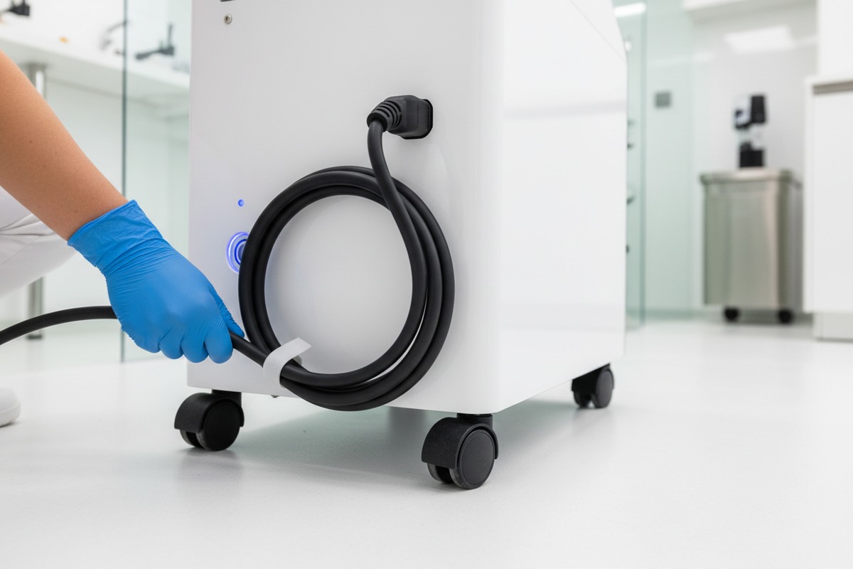
Look for integrated cord management channels, retractable cable systems, low-profile connectors with strain relief, magnetic cable guides, and overhead routing options. These features keep cords secured along machine bodies and away from high-traffic floor areas.
Integrated Cable Management Systems
Premium shockwave machines include built-in cable routing. Channels molded into the chassis guide cords along non-obstructive paths. This keeps cables tight against the machine body rather than sprawling across floors.
Key features to evaluate:
- Recessed channels: Cords sit below surface level
- Clip systems: Secure cables at multiple points
- Velcro straps: Allow quick adjustments
- Magnetic guides: Enable tool-free repositioning
Retractable Cable Mechanisms
Some high-end units feature retractable power cables 6 similar to vacuum cleaners. Technicians pull out needed length, then the mechanism retracts excess automatically.
This system eliminates loose cable loops entirely. However, retraction mechanisms add complexity and potential failure points. We recommend models with user-serviceable retraction units for easier maintenance.
Connector Profile Analysis
The connector itself impacts obstruction potential. Large, bulky connectors protrude from machine surfaces. They catch on passing carts and clothing. Low-profile connectors sit nearly flush, reducing snag risks.
| Connector Type | Protrusion Height | Strain Relief | Durability Rating |
|---|---|---|---|
| Standard IEC | 45-55mm | Basic | Moderate |
| Right-Angle IEC | 25-30mm | Moderate | Good |
| Flush-Mount | 10-15mm | Integrated | Excellent |
| Twist-Lock | 35-40mm | Superior | Excellent |
| Magnetic | 5-10mm | N/A (breakaway) | Limited |
Floor-Level vs. Elevated Routing
Two philosophies exist for cord routing. Floor-level approaches use cord covers and floor channels. Elevated approaches route cables overhead or along wall tracks.
Floor-level routing works well in permanent installations. The cords stay hidden under protective covers. However, this approach fails in rooms where equipment moves frequently.
Elevated routing keeps cords completely off floors. Ceiling-mounted retractors and wall-track systems achieve this goal. The upfront installation cost is higher, but long-term safety improves dramatically.
Movement Pattern Mapping
Before selecting a machine, map your technicians' typical movement patterns. Identify high-traffic zones around treatment beds. Note where rolling equipment travels. This analysis reveals optimal cord routing paths.
Our engineering team can review your floor plans during the consultation phase. We recommend cord management solutions based on actual workflow requirements rather than generic assumptions.
Is the power interface design robust enough to prevent damage when I move the machine between treatment rooms?
When we ship shockwave machines internationally, they endure rough handling. Forklifts. Loading docks. Delivery trucks. If a power interface survives that journey, it can handle inter-room movement. But many manufacturers cut corners here.
Robust power interface design for mobile use requires reinforced housing, strain-relief cable boots, recessed or protected port locations, medical-grade connector ratings (minimum 5000 insertion cycles), and impact-resistant materials around connection points.

Durability Testing Standards
Medical equipment undergoes standardized durability testing. The IEC 60601 standard 7 specifies requirements for electrical connections. However, not all manufacturers test to the same rigor.
Ask potential suppliers for specific test data:
- Insertion cycle ratings: How many connect/disconnect cycles before failure?
- Pull strength: What force does the cable withstand before disconnecting?
- Impact resistance: Can the connector survive a 1-meter drop?
- Flex testing: How many bend cycles does the cable endure?
Material Quality Indicators
The materials around power interfaces reveal durability expectations. Cheap ABS plastic cracks under impact. Medical-grade polycarbonate 8 absorbs shocks without fracturing.
| Material | Impact Resistance | Temperature Range | Cost Level |
|---|---|---|---|
| ABS Plastic | Low | -20°C to 80°C | Budget |
| Polycarbonate | High | -40°C to 120°C | Mid-range |
| Glass-Filled Nylon | Very High | -40°C to 150°C | Premium |
| Aluminum Housing | Excellent | -50°C to 200°C | Premium+ |
Strain Relief Engineering
The junction between cable and connector experiences maximum stress during movement. Quality strain relief distributes this stress along a longer cable section rather than concentrating it at one point.
Look for:
- Boot length: Minimum 50mm of flexible strain relief
- Bend radius control: Prevents sharp kinks that damage conductors
- Internal anchoring: Cable secured inside connector housing
Our factory uses over-molded strain relief on all power cables. This creates a seamless transition from cable to connector, eliminating weak points.
Protective Port Features
Recessed ports protect connectors from side impacts. If someone bumps the machine against a doorframe, the recessed area absorbs contact before the connector does.
Some designs include hinged covers that close when cables are disconnected. This prevents dust and debris from contaminating port contacts during storage or transport.
Wheel and Caster Integration
Machine mobility affects power interface stress. Hard casters transmit floor vibrations directly to the chassis. Shock-absorbing casters reduce this transmission significantly.
When evaluating a machine for inter-room use, test the caster quality. Roll it across typical floor surfaces. Note how much the chassis vibrates. Excessive vibration loosens electrical connections over time.
Our premium shockwave units feature medical-grade casters with 75mm rubber wheels. These roll smoothly over thresholds and uneven surfaces without jarring the internal components.
Conclusion
Power interface design significantly impacts daily salon operations. Evaluating port location, customization options, cord management, and durability before purchasing prevents costly workflow problems later. Choose machines engineered for your specific clinic environment.
Footnotes
1. Provides information on compact shockwave systems for musculoskeletal pain treatment. ↩︎
2. Discusses power adapter configurations and safety standards for medical devices. ↩︎
3. Explains hospital-grade power cord requirements and standards for medical equipment. ↩︎
4. Explains what ODM means in medical device manufacturing and its importance for customization. ↩︎
5. Authoritative source (BSI) explaining CE marking and certification for medical devices. ↩︎
6. Describes retractable cords, their benefits, and use in medical devices for space-saving and mobility. ↩︎
7. Provides a comprehensive overview of the IEC 60601 standard for medical electrical equipment safety. ↩︎
8. Highlights the properties of medical-grade polycarbonate, including strength, heat resistance, and toughness for medical devices. ↩︎

 English
  Español de México
  Deutsch
  Français
  العربية
  Русский