When our production lines first started assembling pressotherapy machines, we quickly learned that the PCB inside determines whether the machine delivers consistent pressure cycles or fails in the middle of a treatment session IEC 60601 compliance 1. The complexity of controlling multiple pneumatic channels, reading pressure sensors, and managing user interfaces all comes down to one thing: the quality of PCB design expertise behind your supplier.
To evaluate supplier PCB design expertise for pressotherapy machines, verify their ISO 13485 certification, confirm IEC 60601 compliance knowledge, assess their experience with HDI layouts and EMI control, request AOI and X-ray testing documentation, and audit their design control processes for medical-grade reliability.
This guide walks you through the critical questions to ask, the benchmarks to measure, and the documentation to request before signing any contract EMI/EMC compliance 2. Let’s start with understanding how to assess your supplier’s engineering depth.
How can I verify that the supplier's PCB design team has the engineering depth I need for reliable pressotherapy machines?
When we first started vetting PCB suppliers overseas, we discovered that flashy websites and large factory photos don't tell you anything about actual engineering capability in-circuit test (ICT) data 3. A pressotherapy machine demands precise control over air pumps, valves, and pressure sensors. One poorly designed circuit can cause the machine to over-inflate a compression sleeve—potentially injuring the user.
Verify engineering depth by examining the supplier's certifications (ISO 13485, IEC 60601 familiarity), reviewing their portfolio of medical device PCB projects, assessing their design control documentation practices, and conducting technical interviews with their engineering staff on topics like EMI control and redundancy design.

Start With Certifications and Standards Knowledge
The first filter is regulatory compliance. A supplier designing PCBs for pressotherapy devices must understand medical device regulations inside and out.
| Certification/Standard | What It Covers | Why It Matters for Pressotherapy |
|---|---|---|
| ISO 13485 | Quality management system for medical devices | Ensures documented design controls and traceability |
| IEC 60601-1 | Electrical safety for medical equipment | Mandates patient protection, leakage current limits |
| FDA 21 CFR Part 820 4 | US Quality System Regulation | Required for US market entry |
| IPC Class 3 5 | High-reliability electronics standards | Defines tighter tolerances for medical PCBs |
According to regulatory experts, "Medical device manufacturers must comply with the FDA's 21 CFR Part 820 regulations. These regulations mandate a comprehensive quality management system (QMS) throughout the device's life cycle, including PCB design."
"60601 is a widely accepted benchmark for medical electrical equipment and compliance with IEC60601-1 has become a requirement for the commercialisation of electrical medical equipment in many countries. Many companies view compliance with IEC 60601-1 as a requirement for most markets."
Assess Design Control Documentation
Don't accept vague answers about quality systems. Request specific documentation.
A capable supplier should provide:
- Design History Files (DHF) 6 samples
- Risk analysis templates aligned with ISO 14971 7
- Change control procedures
- Verification and validation protocols
"ISO 13485 does not define design requirements; it defines process requirements that ensure product quality and regulatory compliance. Designers and PCB manufacturers with a compliant QMS need to follow some important documentation requirements for medical PCBs: Identifying defects and recording solutions: Design defects that are identified before and during manufacturing need to be identified, and ideal solutions need to be recorded. Designers and manufacturers both have a role to play in correcting quality defects and recording solutions."
Technical Interview Questions
When you speak with the supplier's engineers, ask these probing questions:
- How do you handle EMI shielding for boards with both analog sensors and digital communication modules?
- What redundancy mechanisms do you build into safety-critical circuits?
- Walk me through your thermal management approach for prolonged operation cycles.
- How do you ensure pressure sensor signal integrity across varying environmental conditions?
"Redundancy is essential in life-critical devices. It ensures that if one component fails, the device can continue operating. For example, a redundant power supply circuit or a backup communication channel may be necessary to maintain functionality."
Review Their Medical Device Portfolio
Ask for case studies. A supplier with genuine expertise will have examples of similar projects—ideally involving:
- Pneumatic control systems
- Sensor integration
- Wireless connectivity (Bluetooth for app control)
- Battery management for portable units
"Class 2 represents standard electronics, while Class 3 applies to high-reliability products including medical devices. Class 3 requires tighter tolerances, more rigorous inspection, and stricter acceptance criteria for solder joints and component placement."
What technical benchmarks should I use to evaluate the stability of a supplier's PCB architecture?
Our engineering team once received a batch of PCBs that passed visual inspection but failed during thermal cycling tests. The boards worked fine in a controlled environment but showed intermittent failures after just a few hours of continuous operation. That experience taught us that stability benchmarks must go beyond surface-level checks.
Key technical benchmarks include trace width specifications (≤3 mil for compact medical layouts), creepage and clearance distances per IEC 60601 (typically 4mm or more for patient safety), thermal management design for extended sessions, signal integrity for pressure sensors, and EMI/EMC compliance for interference-free operation.

Critical PCB Design Specifications
Pressotherapy machines present unique challenges. The PCB must simultaneously:
- Control multiple pneumatic valves with precise timing
- Process real-time pressure sensor data
- Manage user interface displays
- Support wireless connectivity
- Operate reliably during 30-45 minute treatment sessions
| Specification | Benchmark Value | Impact on Pressotherapy |
|---|---|---|
| Trace Width | ≤3 mil for HDI layouts | Enables compact designs for portable units |
| Creepage Distance | ≥4mm for patient safety | Prevents electrical arcing near user |
| Operating Temperature | -10°C to +50°C | Ensures reliability in clinic and home environments |
| Dielectric Strength | 1500V+ withstand | Protects against electrical breakdown |
| Leakage Current | <0.5mA for patient-connected devices | IEC 60601 safety requirement |
"IEC 60601 sets specific limits for leakage currents (typically below 0.5 mA for patient-connected devices) and insulation resistance to protect users and patients. Dielectric Strength: Ensuring the PCB can withstand high voltages without breakdown, often tested at 1500V or higher depending on the device class. Creepage and Clearance: Maintaining minimum distances between conductive parts to prevent electrical arcing, often 4 mm or more for patient safety."
Thermal Management Considerations
A pressotherapy session typically runs 30-45 minutes. During this time, the PCB continuously operates pumps, processes sensor data, and powers displays. Without proper thermal management, component degradation accelerates.
"While electrical safety is paramount, the power supply also must not run so hot as to cause burns or fires. IEC 60601-1 covers temperature limits for accessible parts and requires fire enclosures for certain components."
Ask your supplier:
- What thermal simulation tools do they use before prototyping?
- How do they validate thermal performance under continuous load?
- What component derating practices do they follow?
Signal Integrity for Pressure Sensors
Accurate pressure readings are non-negotiable. A pressotherapy machine that delivers incorrect pressure levels can cause tissue damage or provide ineffective treatment.
"Core Considerations for Medical PCB Design • Material and stack-up choices aligned to safety and reliability • Signal integrity for low-power sensing and data transmission • Mechanical durability for skin-contact wearables or flexing elements • Moisture and contamination protection through coatings or encapsulation • Biocompatibility, sterilization compatibility, and thermal stability"
The PCB layout must minimize noise coupling between:
- High-current pump drive circuits
- Sensitive analog sensor inputs
- Digital communication buses
EMI/EMC Compliance
"EMC Medical devices must meet EMC standards to prevent interference with other hospital equipment. IEC 60601 is a key standard, ensuring that devices like pacemakers or MRI machines can function without disrupting other critical systems. Special techniques like shielding and filtering are used to prevent EMI in medical PCBs."
Request evidence of:
- EMC simulation results
- Pre-compliance testing reports
- Shielding strategies for wireless modules
How does the PCB design impact my ability to private-label and customize the machine's functionality?
When we work with brand owners who want to differentiate their pressotherapy products, the PCB architecture often becomes the limiting factor. A rigid, closed design locks you into the supplier's predefined features. A modular, well-documented design opens doors for customization without complete re-engineering.
PCB design directly impacts customization through modular architecture enabling feature addition, documented firmware interfaces for software modifications, accessible test points for quality validation, flexible I/O configurations for sensor upgrades, and proper design documentation enabling future redesigns or second-source options.

Modular Architecture Benefits
A pressotherapy machine might need:
- Different numbers of compression channels (4, 8, 12, or more)
- Various interface options (touchscreen vs. basic LCD)
- Connectivity choices (Bluetooth, WiFi, or wired only)
- Accessory support (leg sleeves, arm sleeves, abdominal wraps)
| Design Approach | Customization Flexibility | IP Protection Risk |
|---|---|---|
| Monolithic single-board | Low—changes require complete redesign | Lower—all IP on one board |
| Modular multi-board | High—swap modules for different features | Higher—clear functional separation |
| FPGA/programmable | Very high—software-defined features | Medium—requires firmware expertise |
Ask your supplier:
- Can the main control board accommodate additional I/O for future features?
- Are interface protocols documented for third-party accessory development?
- What is the process for firmware modifications?
Documentation Requirements for Private Label
"Supplier evaluation and traceability: For electronics and PCBs, materials and components need to be traceable and have thorough documentation that supports intended device performance."
Request these documents:
- Complete Bill of Materials (BOM) with alternative component options
- Schematic diagrams
- PCB layout files (Gerber or native format)
- Firmware source code or detailed API documentation
- Test specifications and acceptance criteria
Without proper documentation, you become entirely dependent on the original supplier. This creates risk if you need to:
- Switch suppliers due to quality issues
- Add features for market differentiation
- Troubleshoot field failures independently
DFM and DFT Considerations
"Designers must account for bending cycles, moisture barriers, power stability, controlled impedance paths for sensors, and noise reduction around analog front ends. Early discussions on DFM, test coverage, shielding requirements, and conformance testing accelerate development and avoid redesigning cycles that delay clinical evaluation."
Design for Manufacturability (DFM) 10 and Design for Testability (DFT) directly impact your ability to:
- Source PCBs from multiple suppliers
- Maintain consistent quality across production batches
- Scale production volumes efficiently
Long-Term Component Availability
"Durability and Reliability Medical PCBs need to last for 5–10 years without failure. This means they must be made from durable materials that can withstand temperature fluctuations and exposure to body fluids. Additionally, solder joints and components must be resistant to corrosion and degradation over time."
A forward-thinking supplier will:
- Select components with long lifecycle availability
- Document alternative components for critical functions
- Have a component obsolescence management strategy
What specific PCB testing documentation should I request to ensure my machines won't fail after delivery?
After one particularly painful experience with a batch of machines that started failing three months after delivery, we completely overhauled our incoming inspection requirements. The supplier had provided basic test reports, but those reports didn't capture the latent defects that emerged under real-world use conditions.
Request AOI reports for surface defect detection, X-ray inspection results for hidden solder joint analysis, in-circuit test (ICT) data for electrical verification, functional test protocols and results, environmental stress screening records, and full traceability documentation linking each board to component lots and test results.
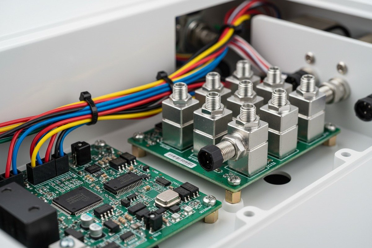
Essential Testing Methods
"PCB X-ray inspection is a non-destructive testing method that uses X-ray imaging to examine the internal structure of a circuit board. Unlike visual inspections, which can only assess surface-level issues, X-ray technology reveals hidden defects such as voids in solder joints, misaligned components, or internal cracks in multi-layer boards. For medical device PCBs, where precision and reliability are critical, this level of scrutiny is essential."
| Test Method | Defects Detected | When to Use |
|---|---|---|
| AOI (Automated Optical Inspection) | Missing components, misalignment, solder bridges | Every board—surface-level screening |
| X-ray Inspection | Hidden solder voids, BGA defects, internal cracks | Complex assemblies with hidden joints |
| ICT (In-Circuit Test) | Opens, shorts, component values | Electrical verification of all boards |
| Flying Probe Test | Connectivity, shorts | Low-volume or prototype runs |
| Functional Test | Actual performance under operating conditions | Final validation before shipment |
AOI and X-ray for Medical PCBs
"For Complex Assemblies: X-ray is essential for detecting hidden defects in high-density assemblies like BGAs. For Critical Applications: Industries requiring utmost reliability, such as aerospace or medical devices, benefit from combining both AOI and X-ray testing."
For pressotherapy machines with:
- BGA or QFN packages (common in modern microcontrollers)
- Multi-layer boards
- High-density component placement
X-ray inspection is not optional—it's essential.
"Every medical PCB must undergo rigorous design validation and multi-stage testing before approval. Automated Optical Inspection (AOI): AOI uses a single 2D camera or two 3D cameras to capture images of the PCB. The captured image is checked against the schematic. If the board does not match the schematic, it is sent to be manually inspected."
Documentation Checklist
Request these specific documents:
Per-Board Traceability:
- Unique board serial number
- Component lot codes linked to that board
- Operator IDs for key process steps
- Test equipment used and calibration status
- Pass/fail results with timestamp
Aggregate Quality Reports:
- First-pass yield rates
- Defect Pareto analysis
- SPC (Statistical Process Control) charts
- Corrective action records for any failures
"X-ray inspection provides documented proof of quality control, helping companies meet FDA compliance requirements under standards like ISO 13485 for medical manufacturing. Detailed X-ray reports can serve as evidence of thorough testing during audits or inspections."
Environmental Stress Screening
For medical devices intended for long-term reliability:
"Devices must meet strict regulatory standards, operate reliably over long lifetimes or single-use cycles, withstand sterilization or biological exposure, and maintain performance under mechanical and environmental stress."
Request evidence of:
- Thermal cycling test results
- Humidity exposure testing
- Vibration testing (especially for portable units)
- Accelerated life testing data
Red Flags in Test Documentation
Watch for these warning signs:
- Generic test reports not linked to specific production batches
- Missing calibration certificates for test equipment
- No traceability from finished board to component suppliers
- Reluctance to share raw test data
- Test coverage that doesn't include all critical functions
"The goal of this evaluation is to determine if the supplier meets your requirements and can be added to your Approved Supplier List (ASL). Nothing related to final product quality should be purchased from suppliers that are not on your ASL, as this puts you at serious risk of bad quality products, audit findings, and regulatory consequences."
Conclusion
Evaluating a supplier's PCB design expertise requires looking beyond certifications to actual engineering capability, testing rigor, and documentation practices. For pressotherapy machines, where patient safety and treatment efficacy depend on precise pneumatic control, these evaluation steps protect both your customers and your brand reputation.
Footnotes
1. Intertek provides information on IEC 60601 standards for medical electrical equipment. ↩︎
2. Discusses the importance of EMC compliance testing for electronic medical devices. ↩︎
3. Found an authoritative article from PCBCart explaining in-circuit testing (ICT). ↩︎
4. Official U.S. government regulation for quality systems in medical device manufacturing. ↩︎
5. Explains IPC Class 3 standards for high-reliability electronics, including medical devices. ↩︎
6. Defines DHF as a compilation of records for medical device design and development. ↩︎
7. PTC explains the international standard for risk management in medical devices. ↩︎
8. Official certification body for medical device quality management systems. ↩︎
9. Analog Devices details creepage and clearance requirements for medical applications under IEC 60601. ↩︎
10. Protolabs explains DFM as designing products to reduce manufacturing cost and ease. ↩︎

 English
 Español de México
 Deutsch
 Français
 العربية
 Русский