Every time our production line ships a batch of shockwave therapy machines overseas, one question keeps us awake: will these units perform flawlessly after enduring harsh shipping conditions, extreme climates, and millions of treatment pulses ISTA 3A 1? The gap between lab performance and real-world reliability has cost many manufacturers their reputation.
To verify shockwave therapy machine reliability, manufacturers must implement comprehensive extreme-condition simulation protocols including accelerated life testing, thermal cycling, vibration testing, humidity exposure, and duty-cycle validation. These tests expose design weaknesses before products reach clinics, ensuring consistent performance across diverse operating environments.
In this guide, we share the exact testing protocols our engineering team uses to validate every shockwave therapy machine sample ASTM D4169 protocols 2. You will learn practical methods to stress-test components and predict long-term reliability.
How can I test if the shockwave machine's internal components will withstand the physical stress of long-distance international shipping?
When our first shipment to Europe arrived with three damaged units, we realized standard packaging tests were not enough. The internal components had shifted during transit, causing circuit board micro-fractures invisible to visual inspection.
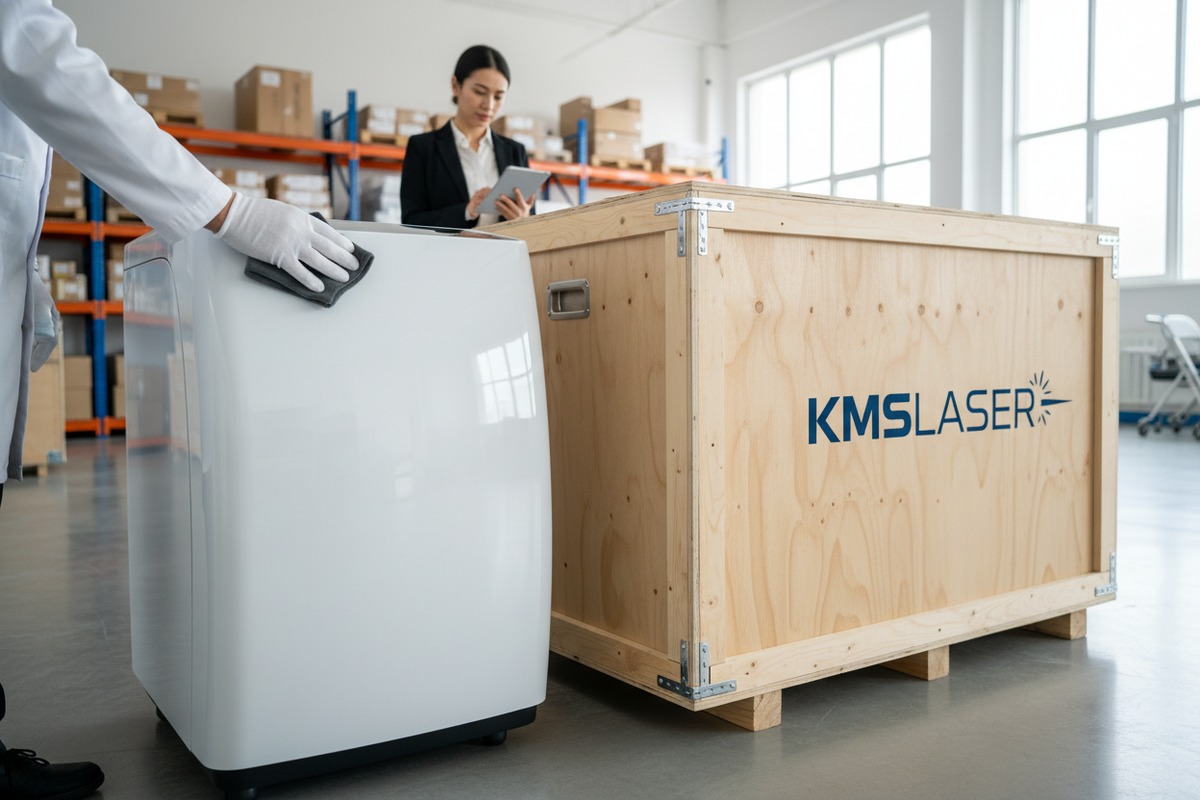
To test shipping durability, subject your shockwave machine to ISTA 3A or ASTM D4169 protocols that simulate real-world transport conditions. This includes random vibration testing, drop tests from multiple orientations, compression testing, and temperature cycling during simulated transit periods exceeding 72 hours.

Understanding Transport Stress Categories
Shipping stress affects shockwave machines in three main ways: mechanical shock, sustained vibration, and environmental exposure. Each category requires specific testing approaches.
Mechanical shock occurs during loading, unloading, and handling. A single drop from 76 cm can generate forces exceeding 100G. Internal components like the pneumatic compressor, capacitor banks, and display screens are vulnerable to such impacts.
Sustained vibration happens throughout the journey. Road transport generates 5-200 Hz frequencies. Air cargo adds 50-500 Hz vibrations. These oscillations can loosen fasteners, fatigue solder joints 3, and wear mechanical linkages.
Environmental exposure includes temperature swings from -20°C to 50°C in cargo holds and humidity spikes during port storage. Condensation forms when containers move between climate zones, potentially causing corrosion.
Practical Testing Protocol
Our engineering team follows a structured approach to shipping simulation:
| Test Phase | Parameters | Duration | Acceptance Criteria |
|---|---|---|---|
| Random Vibration | 5-200 Hz, 0.5 Grms | 3 hours per axis | No loose components, all functions normal |
| Drop Test | 76 cm, 6 faces + 4 edges | 10 drops total | No structural damage, calibration maintained |
| Compression Test | 1000 kg static load | 24 hours | Package integrity, no case deformation |
| Temperature Cycle | -20°C to 50°C | 72 hours, 6 cycles | Electronics function, seals intact |
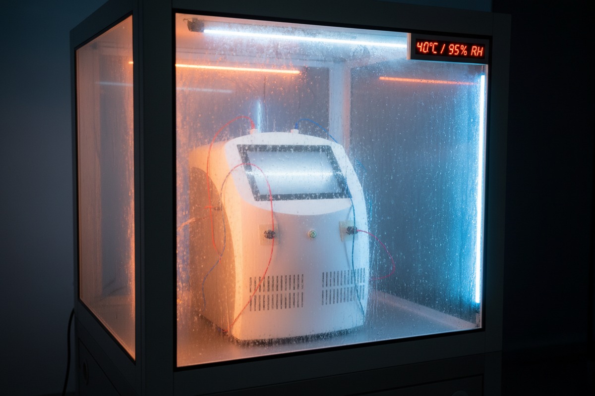
| Humidity Exposure 4 | 95% RH at 40°C | 48 hours | No condensation inside, no corrosion |
Critical Inspection Points
After completing shipping simulation, we inspect these high-risk areas:
The compressor mounting brackets often show first signs of fatigue. Look for hairline cracks at weld points. Check torque on all mounting bolts.
Circuit board solder joints deserve microscopic examination. Cold joints and micro-fractures appear at heavy component connections. Pay special attention to transformer and capacitor leads.
The applicator cable connection point experiences significant stress. Inspect the strain relief, connector pins, and internal wire terminations.
Display screen bezels can crack under vibration. Check for separation between screen and housing. Test touch functionality across the entire surface.
What protocols should I follow to verify the long-term reliability of the applicator handle after millions of pulses?
Our R&D team discovered that applicator failures rarely happen suddenly. They follow predictable degradation curves that proper testing can reveal months before clinical problems appear.
Verify applicator reliability through accelerated life testing that subjects the handle to 2-5 million pulses at maximum energy settings while monitoring acoustic output, temperature rise, and mechanical wear. Track energy flux density drift, trigger mechanism cycles, and housing integrity to establish mean time between failures.

Accelerated Life Testing Methodology
Accelerated life testing 6 compresses years of clinical use into weeks of laboratory testing. The key is applying stress levels that accelerate failure mechanisms without introducing artificial failure modes.
For pneumatic applicators, we increase pulse frequency from clinical 10-15 Hz to test speeds of 20-25 Hz. This doubles the mechanical stress rate while maintaining the same energy levels. Running continuously at 20 Hz, we accumulate 1.7 million pulses per day.
For electromagnetic applicators, we operate at maximum energy settings continuously rather than the variable clinical patterns. This accelerates coil heating and capacitor stress.
Performance Tracking Parameters
| Parameter | Measurement Method | Frequency | Failure Threshold |
|---|---|---|---|
| Energy Flux Density 7 | Hydrophone in water tank | Every 100,000 pulses | >15% drift from baseline |
| Acoustic Peak Pressure | Calibrated pressure sensor | Every 50,000 pulses | >20% reduction |
| Focal Zone Stability | Beam profile mapping | Every 250,000 pulses | >10% shift in focal depth |
| Housing Temperature | Infrared thermometer | Continuous during testing | >60°C surface temperature |
| Trigger Mechanism | Cycle counter, force gauge | Continuous | >30% increase in trigger force |
Component-Specific Inspection Schedule
The applicator contains several wear-prone components that need periodic inspection during accelerated testing:
The projectile or striker assembly experiences direct impact stress with every pulse. Inspect for surface pitting, diameter reduction, and weight loss at 500,000 pulse intervals. Replace when wear exceeds 0.1mm depth.
O-rings and seals degrade from heat and mechanical compression. Check for hardening, cracking, and compression set. Most seals need replacement between 1-2 million pulses.
The transmitter or applicator tip contacts patient skin. Inspect for surface erosion, coating degradation, and coupling efficiency changes. Coating failure affects energy transmission significantly.
Cable connections endure repeated flexing during clinical use. Simulate this by adding articulation cycles during life testing. Inspect wire conductors for work hardening and insulation breakdown.
Establishing Reliability Predictions
Our data from testing hundreds of applicator samples allows us to establish reliability curves. A well-designed applicator should maintain >90% of baseline acoustic output through 2 million pulses. The trigger mechanism should operate within specification for 3 million cycles minimum.
We recommend testing three samples minimum to establish statistical confidence. Record all data points to generate degradation curves. These curves help predict when maintenance or replacement becomes necessary in clinical settings.
How do I evaluate if the machine's cooling system can handle continuous back-to-back treatments without performance drops?
During busy clinic hours, our machines face thermal challenges that standard duty-cycle testing never reveals. We once received a complaint from a sports medicine clinic running 25 treatments daily—their machine started reducing output automatically after the 15th patient.
Evaluate cooling system performance by simulating extreme clinical workloads with back-to-back 30-minute treatment sessions at maximum settings. Monitor internal component temperatures, acoustic output stability, and thermal protection activation throughout an 8-hour simulated shift to identify thermal limitations.
Thermal Load Analysis
Shockwave therapy machines generate heat from three main sources: the compressor or electromagnetic coil, power electronics, and the applicator itself. Understanding heat flow helps design effective cooling validation tests.
The compressor in pneumatic systems converts electrical energy to mechanical motion with 60-70% efficiency. The remaining 30-40% becomes heat. At maximum settings, a typical compressor generates 200-400 watts of thermal load continuously.
Power electronics including capacitors, MOSFETs, and transformers add another 50-150 watts depending on pulse frequency and energy level. These components have maximum operating temperatures around 85-105°C.
The applicator generates localized heat at the impact zone. This heat transfers back through the handle, potentially causing user discomfort and affecting seals and lubricants.
8-Hour Shift Simulation Protocol
Our thermal validation protocol replicates realistic clinic operations:
| Phase | Activity | Duration | Monitoring |
|---|---|---|---|
| Warm-up | 500 shots at 3 Bar, 10 Hz | 10 minutes | Baseline temperatures |
| Session Block 1 | 5 treatments, 2000 shots each at max settings | 2 hours | Internal temps every 5 minutes |
| Short Break | Machine idle, cooling | 15 minutes | Thermal recovery rate |
| Session Block 2 | 5 treatments, 2000 shots each at max settings | 2 hours | Compare to Block 1 outputs |
| Lunch Break | Machine idle | 60 minutes | Full thermal recovery check |
| Session Block 3 | 5 treatments, 2000 shots each at max settings | 2 hours | Cumulative heat effects |
| Short Break | Machine idle, cooling | 15 minutes | Recovery rate comparison |
| Session Block 4 | 5 treatments, 2000 shots each at max settings | 2 hours | End-of-day performance |
Critical Temperature Monitoring Points
Place temperature sensors at these locations:
Compressor cylinder head or electromagnetic coil core—the primary heat source. Maximum acceptable temperature varies by design but typically should not exceed 80°C.
Capacitor bank housing—electrolytic capacitors lose lifespan rapidly above 65°C. Every 10°C increase above rated temperature halves capacitor life.
Control board processor—most microprocessors have thermal throttling above 85°C. Performance degradation occurs before this point.
Applicator handle grip area—user comfort requires surface temperatures below 45°C. Higher temperatures cause operator fatigue and may indicate internal component overheating.
Exhaust air temperature—compare inlet and outlet air temperatures. The difference indicates cooling system effectiveness. A decreasing temperature differential during extended operation suggests reduced cooling capacity.
Performance Correlation
Track acoustic output alongside temperature measurements. Create a correlation chart showing output versus temperature rise. Well-designed machines maintain >95% output through the full temperature operating range. If output drops correlate with temperature increases, the cooling system needs improvement.
Can I simulate extreme temperature and humidity fluctuations to ensure the electronics won't fail in different regional climates?
Our machines ship to clinics from humid Singapore to dry Arizona, from cold Norway to hot Brazil. When we started tracking regional failure rates, the correlation with climate became impossible to ignore.
Simulate climate extremes through environmental stress screening that cycles the machine through -10°C to 50°C temperature ranges and 20% to 95% relative humidity levels. Test electronics functionality at each extreme, during transitions, and after condensation events to validate global deployment readiness.
Climate Challenge Categories
Different climates stress electronics in unique ways:
Hot-dry climates cause thermal expansion, plastic embrittlement, lubricant evaporation, and increased electrical resistance in connections.
Hot-humid climates promote corrosion, fungal growth, electrical leakage paths, and contact oxidation. Condensation during cooling cycles is particularly damaging.
Cold climates reduce battery performance, increase plastic brittleness, cause lubricant thickening, and create condensation during warm-up.
Rapid transitions between air-conditioned interiors and outdoor conditions create thermal shock and condensation inside the device.
Environmental Test Chamber Protocol
| Test Condition | Temperature | Humidity | Duration | Test Points |
|---|---|---|---|---|
| Cold Start | -10°C | 30% RH | 4 hours soak | Power-on, calibration check, full function test |
| Cold-to-Warm Transition | -10°C to 25°C | 30% to 50% RH | 2 hours ramp | Monitor for condensation, check function every 30 min |
| Standard Reference | 25°C | 50% RH | 1 hour | Baseline performance measurement |
| Hot-Dry Extreme | 50°C | 20% RH | 4 hours soak | Full function test, thermal protection response |
| Hot-Humid Extreme | 40°C | 95% RH | 4 hours soak | Electrical safety check, function test |
| Condensation Simulation | 40°C to 20°C | 95% RH | 1 hour rapid drop | Inspect for internal condensation, insulation resistance |
| Recovery | 25°C | 50% RH | 2 hours | Full function verification, calibration check |
Electronics Vulnerability Assessment
Circuit boards suffer most from humidity-related failures. Inspect for:
Dendritic growth between traces—silver or tin dendrites grow across insulation barriers in humid conditions when voltage is present. This causes intermittent shorts that are difficult to diagnose.
Corrosion on connectors—gold plating prevents corrosion but wear exposes base metals. Check connector contact surfaces for discoloration.
Electrolytic migration—ionic contamination from flux residue combines with moisture to create conductive paths. Proper cleaning during manufacturing prevents this.
Relay contact oxidation—relays controlling high-current circuits can develop oxide layers on contacts. This increases resistance and causes heating.
Conformal Coating Verification
Many manufacturers apply conformal coating 9 to protect circuit boards. Verify coating effectiveness by:
Visual inspection under UV light—many coatings fluoresce, revealing coverage gaps.
Insulation resistance measurement before and after humidity exposure—resistance should remain above 100 megohms.
Adhesion testing—coating should not peel after thermal cycling.
Coverage verification—critical components should have complete coating coverage with no pinholes.
Conclusion
Extreme condition simulation separates reliable shockwave therapy machines from failures waiting to happen. Our protocols for shipping stress, applicator life testing, thermal validation, and climate simulation provide the framework for comprehensive reliability verification.
Footnotes
1. Describes ISTA 3A, a general simulation test for packaged products in parcel delivery systems. ↩︎
2. Explains ASTM D4169, a standard packaging test for evaluating shipping container performance. ↩︎
3. Reviews research on lead-free solder joint reliability and influencing factors like temperature and vibration. ↩︎
4. Explains humidity testing, its importance, and lists common industry standards for electronics. ↩︎
5. Provides an overview of key vibration test standards across various industries. ↩︎
6. Explains the concept and purpose of accelerated life testing for product reliability. ↩︎
7. Replaced with an article specifically defining and explaining Energy Flux Density within the context of shockwave therapy. ↩︎
8. Replaced with an authoritative manufacturer’s resource that provides an estimated life calculator and explanation for electrolytic capacitors. ↩︎
9. Explains conformal coating as a polymeric film protecting circuit boards from adverse environmental conditions. ↩︎

 English
 Español de México
 Deutsch
 Français
 العربية
 Русский